Getting Started
In this quick tutorial we will go through one of the XENSIV™ PAS CO2 sensor examples available using the Shield2Go or the Miniboard and the XMC microcontroller family in Arduino.
Required Hardware
Name |
Picture |
|---|---|
|
|
|
|
|
|
|
|
Pin headers (included with the XMC 2Go) |
|
Micro-USB to USB A cable |
In case of using the miniboard, the following items are also required:
Jumper cables
12V DC power supply
Required Software
Software Installation
Install Arduino IDE. If you are new to Arduino, please download the program and install it first.
Install XMC Board. The official Arduino boards are already available in the Arduino software, but other third party boards as the Infineon XMC MCU based need to be explicitly included. Follow the instructions in the link to add the XMC board family to Arduino. Do not forget to install as well the JLink software.
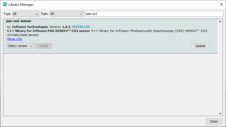
Install the library. In the Arduino IDE, go to the menu Sketch > Include library > Library Manager. Type XENSIV PAS CO2 and install the library.
Hardware Setup
For this example we are going to use the I2C interface.
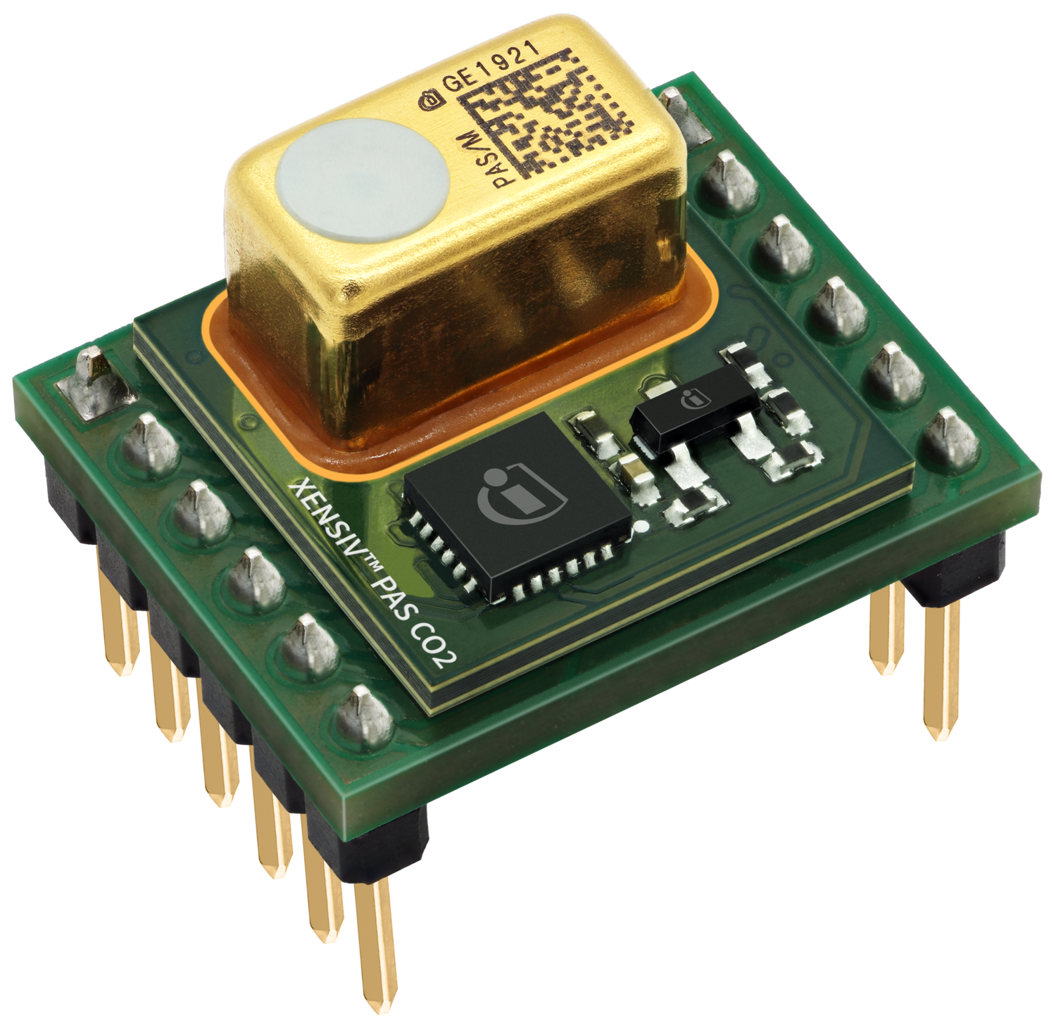
A. Shield2Go
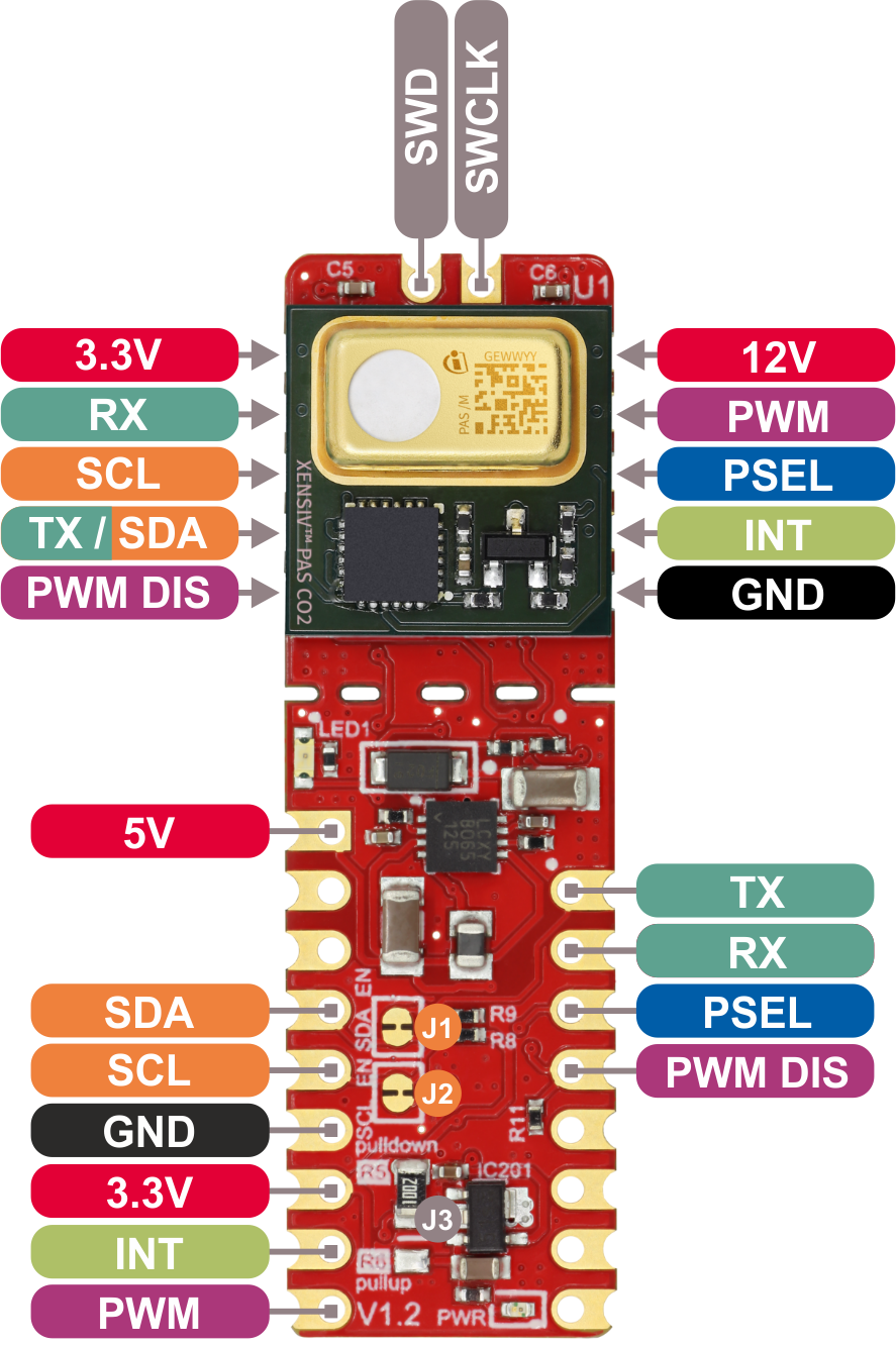
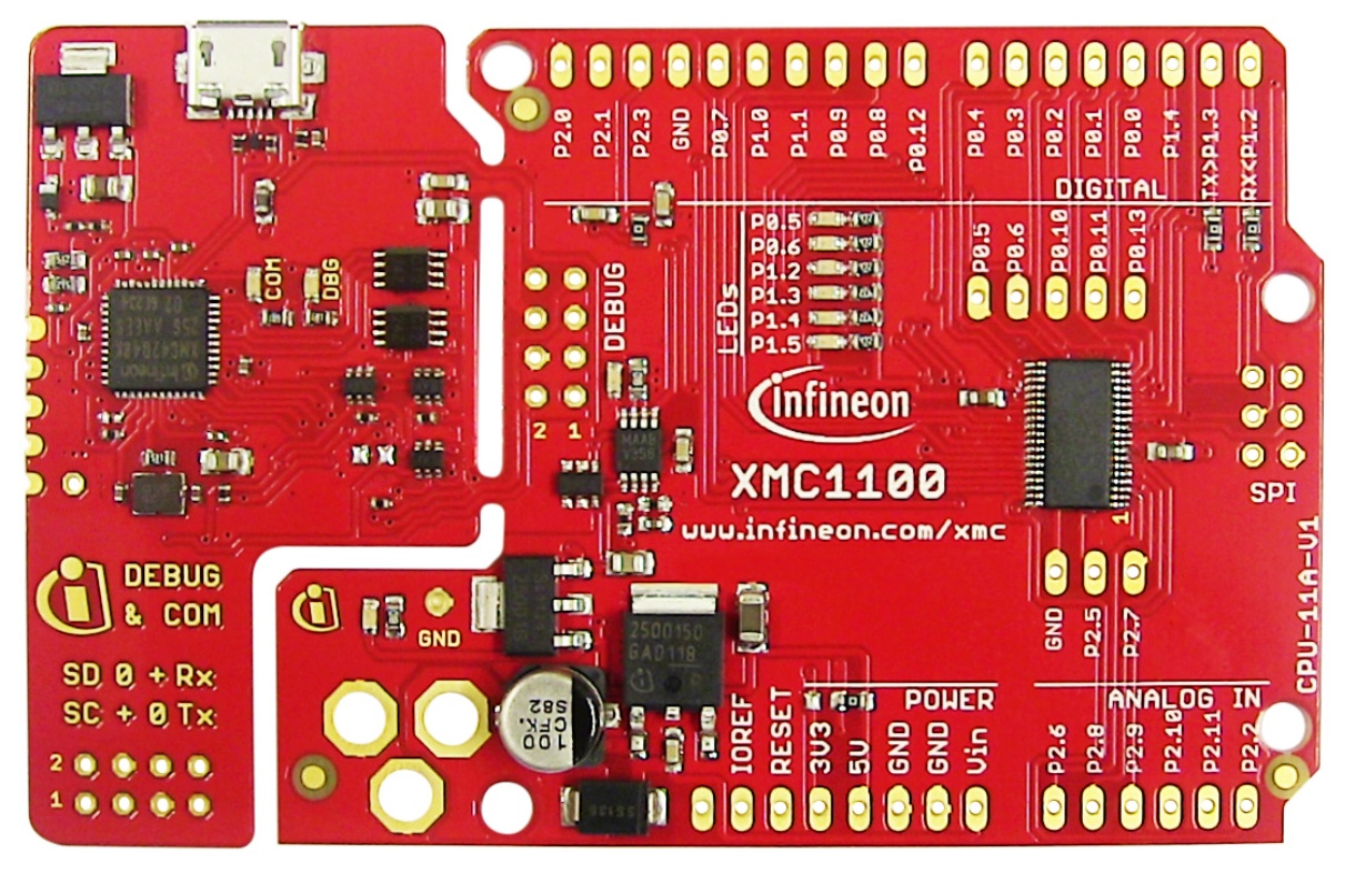
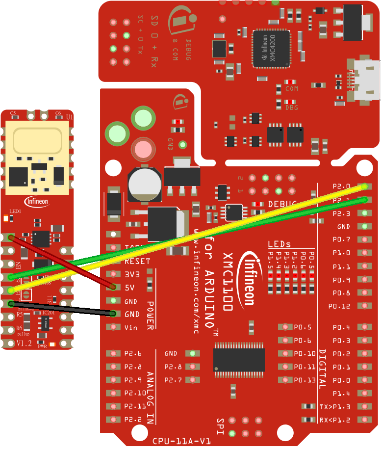
If you are using the XENSIV™ PAS CO2 Sensor Shield2Go, it is recommended to use a microcontroller which provides a 5V output. In this tutorial, the XMC11000 Boot Kit is used. Connect the shield and the eval kit as in the following wiring diagram:
Be sure that the corresponding solder jumper are set for I2C mode, and PSEL is pulled to GND. For this example it is not required, but consider connecting the interrupt signal to the pin 2(P1.4) or 3(P0.0) of the XMC1100 Boot Kit for appliations that require interrupts. Check the Shield2Go Manual for complete details.
Then, simply connect the eval kit to the computer with the USB cable.
Warning
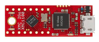
Alternatively, the XMC 2Go can be used by stackin the sensor shield on top. But the XMC 2Go V1 does not support 5V signal, as required by the XENSIV™ PAS CO2 Sensor Shield2Go. Thus, if XMC 2Go is used, keep in mind that an additional 5V signal needs to be provided to the 5V pin of the XENSIV™ PAS CO2 Sensor Shield2Go.
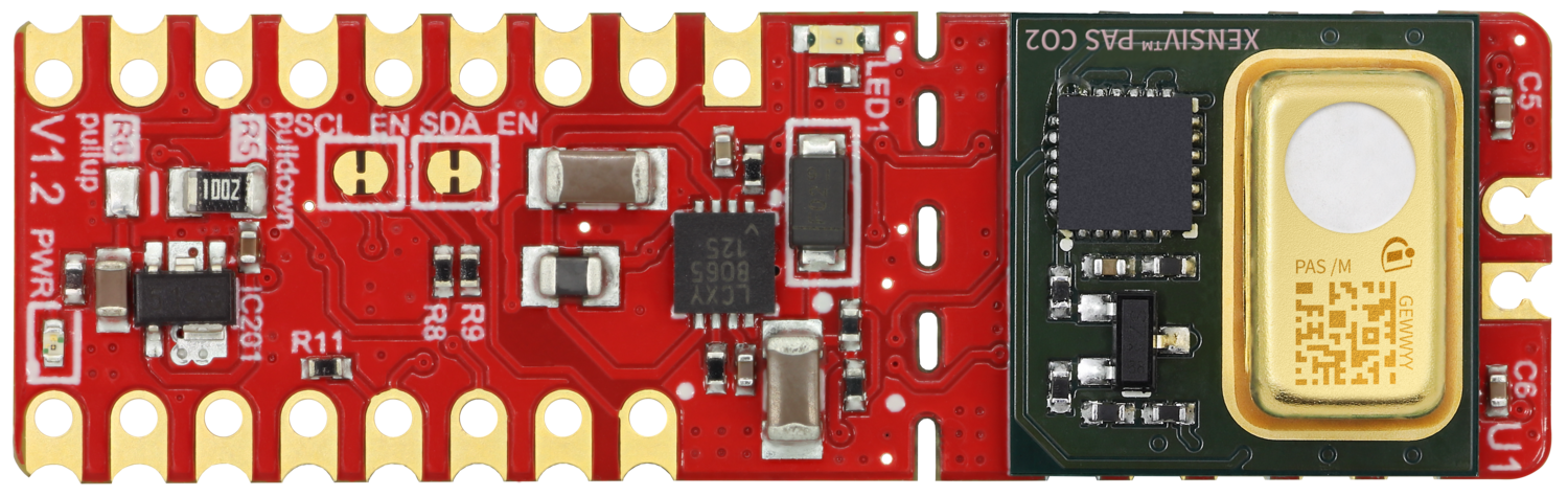
B. Miniboard
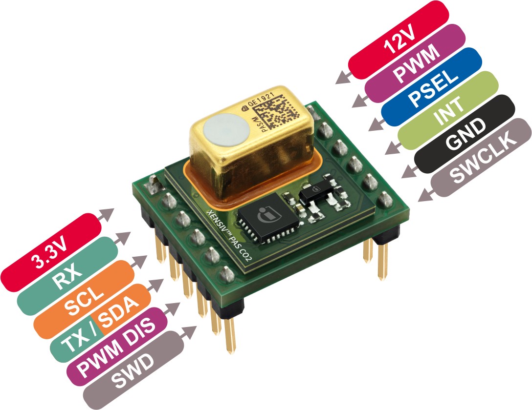
In order to use the I2C interface we need to add a 10 Kohm pull-up resistors to the SDA and SCL lines, and a 12VDC voltage needs to be additionally provided to VDD12V pin. Connect the boards as shown in the following diagram:
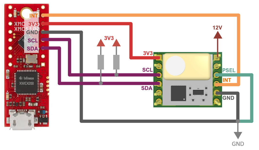
You need to provide a 12V DC signal to for the emitter. Then, simply connect it to the computer with the USB cable.
Note ⚠️ : If the pin headers provided are not press-fit you will need to solder them on the corresponding boards. Otherwise, use your preferred way of connecting the hardware.
Ready To Go!
With everything ready, now we are going to upload and run one of the library examples.
Select the board
Once installed the XMC board family, you can select one of the supported board from the menu Tools > Board:. Choose the XMC1100 XMC2Go or XMC1100 Boot Kit depending on your hardware setup (Tools > Board > XMC Family > XMC1100 XMC2Go/XMC1100 Boot Kit).
Open the example
With the library installed in the Arduino IDE, you can include it from the menu Sketch > Include Library > XENSIV PAS CO2. The header
#include <pas-co2-ino.hpp>will be added to your sketch. In this case, open and run one of the examples provided in File > Examples > XENSIV PAS CO2.Let´s try the continuous mode example: File > Examples > XENSIV PAS CO2 > continuous-mode.
Build and run the example
Select the proper COM port ( Tools > Port), and then verify
 the example and upload it the target
  .
.Finally, we can check the monitor output
 . Do not forget to select the proper baudrate for the serial terminal. You can blow into the sensor to see how the CO2 values change 😃.
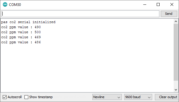
What’s next?
This is just the start 🚀 !
Check out the rest of the available library examples and find out more about the library functions in the API reference section.